
Robotics hardware is weight-sensitive in a way fixed industrial equipment is not: every gram on a moving arm is torque the motor has to produce and energy the battery has to carry. The enclosure therefore has to be thin-walled and stiff, carry accurate mounting datums for sensors and drives, and often dissipate heat from a servo drive in the same volume. Extruded profile plus precision machining is usually the right answer.
What makes this enclosure difficult
These are the failure modes we see most often in this application — and the ones we design against from the first section drawing:
- Weight directly costs performance. On a moving axis, enclosure mass multiplies through the whole duty cycle.
- Mounting datums have to be accurate. Sensor and drive alignment depends on machined features holding position relative to each other.
- Heat in a sealed moving assembly. Servo drives dissipate into a housing with limited airflow.
- Cable management is part of the design. Cable ducts and strain relief are often expected in the structure itself.
How we handle it
Thin-wall sections for stiffness at low mass
We routinely run 0.3–0.8 mm walls with thickness held to ±0.02 mm, so you can remove material without losing predictable section behaviour. Ribs and chambers are extruded rather than machined, which is how stiffness is recovered without adding mass.
Datum faces machined in one setup
Mounting faces, sensor seats and threaded holes are machined in the same fixturing, so positional relationships hold instead of accumulating across operations. For vision and encoder mounting this is usually the deciding factor.
Cable and duct features designed into the section
Cable channels, cover grooves and strain-relief features can be extruded features, removing separate parts and assembly steps. We look for these during DFM review because they are cheap in the die and expensive to add later.
Thermal path for sealed drives
Where a servo drive mounts to the housing, we machine the interface for flatness so the thermal path is reliable, and propose fin geometry on the external surface where convection is available.
±0.005 mm cut-to-length for repeatable frames
Structural profiles arrive at length, so frame and enclosure assemblies build repeatably without shimming or trimming.
Capability that matters here
| Parameter | Typical capability | Why it matters |
|---|---|---|
| Wall thickness | 0.3 – 0.8 mm | Low mass on moving axes |
| Wall thickness tolerance | ±0.02 mm | Predictable stiffness |
| Datum face machining | Same setup as threads and seats | Sensor and drive alignment |
| Inner / outer diameter tolerance | ±0.04 mm | Repeatable joint and bearing fit |
| Cut-to-length accuracy | ±0.005 mm | Frame assembly without shimming |
| Integrated features | Cable ducts, cover grooves, ribs extruded | Fewer parts, fewer assembly steps |
Typical parts we make for this industry
- Servo drive and motor controller housings
- Machine vision camera bodies
- AGV and AMR controller enclosures
- Collaborative robot joint and link covers
- Encoder and sensor housings
- Conveyor and linear module structural profiles
Material and finish
6063-T5 where finish and fine section detail matter; 6061-T6 or 6082 where the enclosure is load-bearing, carries threaded connections under vibration, or forms part of a structural link.
Our polish-free 6063 route runs primary billet from a state-owned mill through ceramic filtration, degassing and homogenising, so the profile goes straight to 180# blasting and anodising with no polishing stage — typically around 15% less finishing cost. We deliberately do not take high-pressure die-casting work; all capacity goes into extruded profile and precision machining.
Questions buyers in this industry ask
Can you keep the enclosure light without losing stiffness?
Yes, by putting the stiffness into the section rather than the wall. Ribs, chambers and cover grooves are extruded features, so the geometry carries the load while the wall stays thin. We routinely run 0.3–0.8 mm walls with thickness held to ±0.02 mm.
How accurate are the mounting datums for sensors and drives?
Mounting faces, sensor seats and threaded holes are machined in the same fixturing, so positional relationships hold rather than accumulating across separate operations. Inner and outer diameters are held to ±0.04 mm. Dimensional reports are available on request.
Can cable management be part of the extrusion?
Usually yes, and it is worth doing. Cable channels, cover grooves and strain-relief features can be extruded directly into the section, which removes separate parts and assembly steps. We look for these opportunities during the free DFM review.
Where we ship these
Other industries we serve
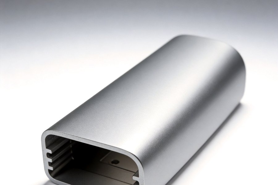
Heat Sink & Thermal Enclosures
Extruded aluminium heat sink enclosures with 0.3 mm fins, machined mounting faces at 0.05 mm flatness and polish-free 6063…
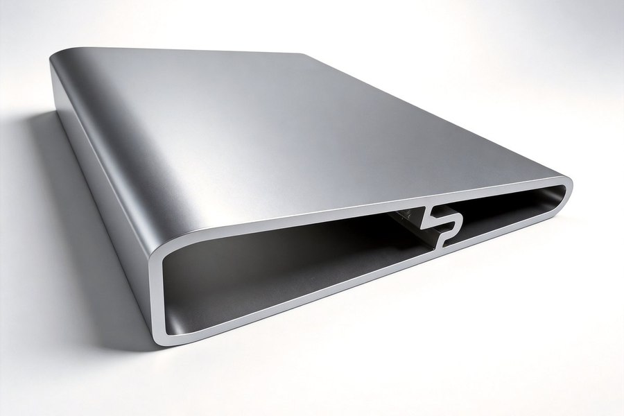
Energy Storage & Battery Enclosures
Extruded aluminium enclosures for portable power stations, home storage modules and BMS control boxes — 0.5–2.0 mm walls, ±0.005…
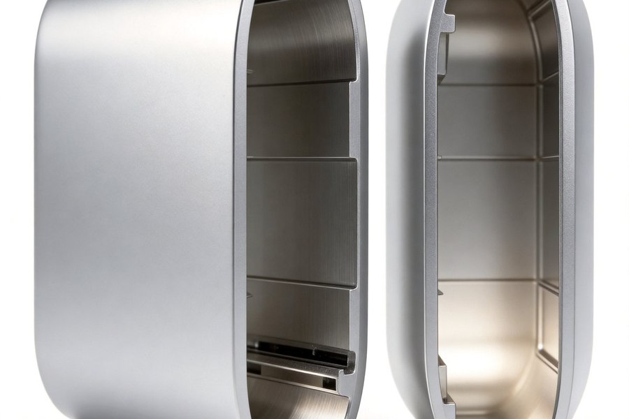
Optical Module & 5G Telecom Enclosures
Tight-tolerance extruded enclosures for 400G/800G optical modules, 5G AAU heat sinks and baseband units — ±0.04 mm bores, 0.3 mm…
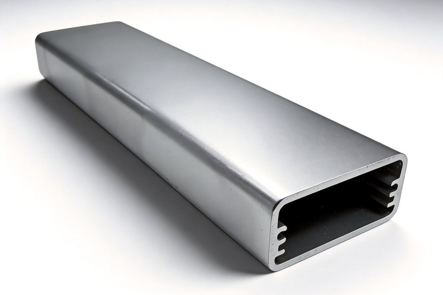
Automotive Electronics Enclosures
Vibration and temperature-cycled aluminium housings for on-board chargers, ECUs, display frames and auxiliary lighting —…
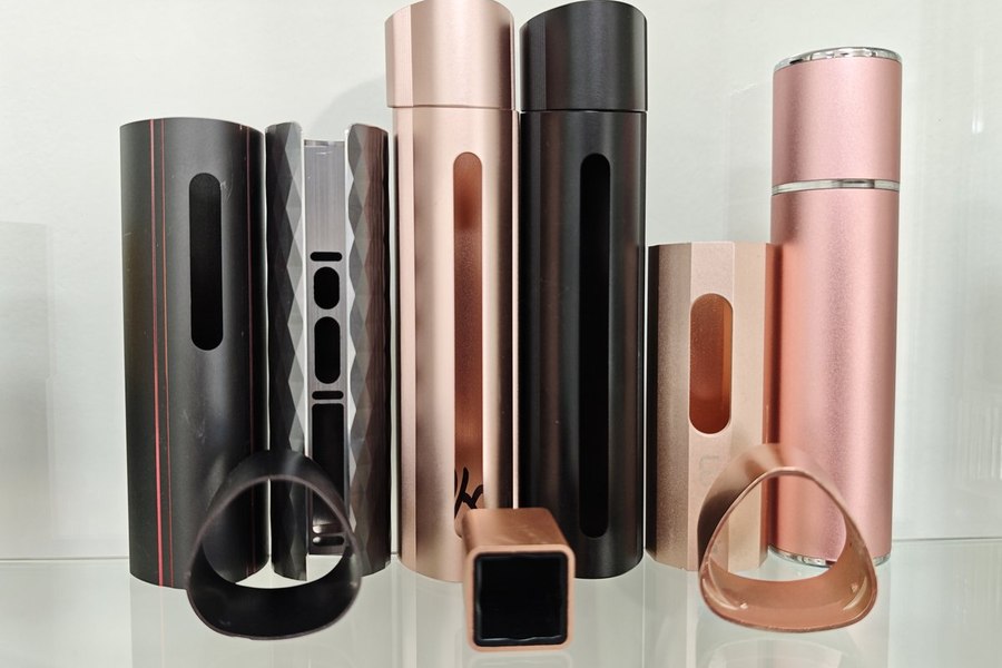
Medical & Beauty Device Enclosures
Cosmetic-grade aluminium housings for beauty instruments, hair styling tools and portable medical devices — polish-free 6063,…
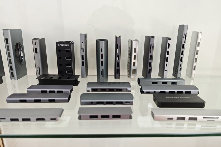
3C Consumer Electronics Enclosures
High-volume aluminium shells for external SSDs, docking stations, power banks and wireless chargers — ±0.005 mm cut-to-length…
Send your assembly drawing and datum requirements — we will review the section and quote tooling within one working day.