
Every generation of power electronics packs more watts into less space, and the enclosure ends up doing two jobs at once: holding the assembly together and moving the heat out. An extruded aluminium profile is still the most cost-effective way to do both — the fin geometry is defined by the die rather than by machining time, so once the tool exists the marginal cost of a fin is almost zero. We design, extrude, machine and finish these housings entirely in-house.
What makes this enclosure difficult
These are the failure modes we see most often in this application — and the ones we design against from the first section drawing:
- Fin geometry is limited by the extrusion process. Too tall and thin, and the die lips deflect or the fins wave; too thick, and you waste metal and airflow area. Getting the aspect ratio right is a design decision, not a machining one.
- Thermal contact resistance is invisible until it fails. A mounting face that is not flat, or is too rough, adds an air gap that can dominate the whole thermal budget regardless of how good the fins are.
- Assembly joints re-introduce resistance. Multi-part heat sink assemblies that bolt together across a seam lose performance at every interface.
- Finishing changes thermal behaviour. A thick powder coat can act as an insulator, while black anodising improves radiative cooling — the finish has to be chosen as part of the thermal design, not after it.
How we handle it
Fin section co-designed with your thermal model
Send the target thermal resistance and the available envelope, and our engineers propose a fin pitch, thickness and height that the press can actually hold in volume. Typical extruded fins run 0.3–1.2 mm thick with heights up to about 60 mm; we will tell you honestly when a geometry needs a different approach rather than quote something we cannot repeat.
0.3 mm ultra-thin walls for more surface per gram
We stably mass-produce 0.3 mm wall sections, which lets you raise fin density inside the same envelope. More surface area per unit weight means lower thermal resistance without increasing the size or material cost of the housing.
Machined mounting face, not an as-extruded one
The interface to your power device is CNC-milled to controlled flatness around 0.05 mm and a fine surface finish, so the thermal compound layer stays thin and uniform. Where the design allows, we integrate the mounting pad into the profile so there is no bolted seam in the heat path.
Polish-free 6063 that is also thermally clean
Primary 6063 billet from a state-owned mill, ceramic-filtered, degassed and homogenised — no sand holes or weld lines for heat flow to detour around. The profile goes straight to 180# blasting and anodising with no polishing stage, which removes roughly 15% of finishing cost.
Finish selected for the thermal strategy
Natural or black anodising for convective and radiative cooling, or powder coating where the enclosure is also a visible exterior part. We flag it early if a specified coating thickness would measurably insulate a critical surface.
Capability that matters here
| Parameter | Typical capability | Why it matters |
|---|---|---|
| Fin thickness | 0.3 – 1.2 mm | Higher fin density in the same envelope |
| Fin height | Up to approx. 60 mm | Sets the available convection area |
| Aspect ratio guidance | Up to approx. 15:1 | Beyond this the die lips deflect in volume |
| Mounting face flatness | Around 0.05 mm after machining | Keeps the thermal compound layer thin |
| Cut-to-length accuracy | ±0.005 mm | Repeatable stack-up in automated assembly |
| Base alloy | 6063-T5 (6061 on request) | ~209 W/m·K thermal conductivity |
Typical parts we make for this industry
- IGBT and MOSFET power module heat sinks
- On-board charger and DC-DC converter housings
- LED driver and high-bay luminaire heat sinks
- Optical module and transceiver heat sink shells
- Energy storage PCS and inverter cooling housings
- Industrial power supply and UPS enclosures
Material and finish
6063-T5 is the default — it extrudes into fine fin detail and anodises evenly. Where the enclosure also carries structural load or needs higher strength after machining, we move to 6061-T6 and re-quote the section, because the finer fin detail of 6063 is no longer available at the same tolerance.
Our polish-free 6063 route runs primary billet from a state-owned mill through ceramic filtration, degassing and homogenising, so the profile goes straight to 180# blasting and anodising with no polishing stage — typically around 15% less finishing cost. We deliberately do not take high-pressure die-casting work; all capacity goes into extruded profile and precision machining.
Questions buyers in this industry ask
Can you hit a target thermal resistance rather than just a drawing?
Yes, and it is usually the better way to start. Give us the dissipated power, allowable case temperature, airflow condition and envelope, and we will propose a fin section and tell you the predicted performance. If your target cannot be met by extrusion alone we will say so at that stage instead of shipping parts that miss spec.
Is an extruded heat sink cheaper than a machined or die-cast one?
For medium and high volumes, almost always. The fin geometry is created by the die rather than by cutting time, so per-piece cost drops sharply once tooling is amortised. We do not take high-pressure die-casting work at all — our capacity is deliberately concentrated in extruded profile and precision machining.
How do you control batch-to-batch consistency on fin geometry?
The die defines the section, so the main variables are press stability and post-extrusion handling. We run two automated extrusion lines with in-process checks, and hold wall thickness to ±0.02 mm against a GB standard of ±0.05 mm. Dimensional reports can be supplied with each batch.
Where we ship these
Other industries we serve
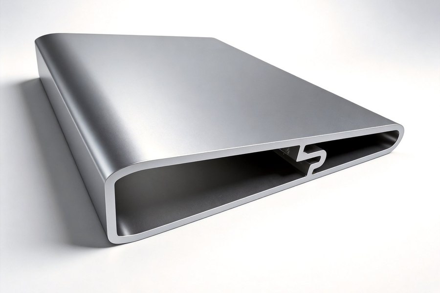
Energy Storage & Battery Enclosures
Extruded aluminium enclosures for portable power stations, home storage modules and BMS control boxes — 0.5–2.0 mm walls, ±0.005…
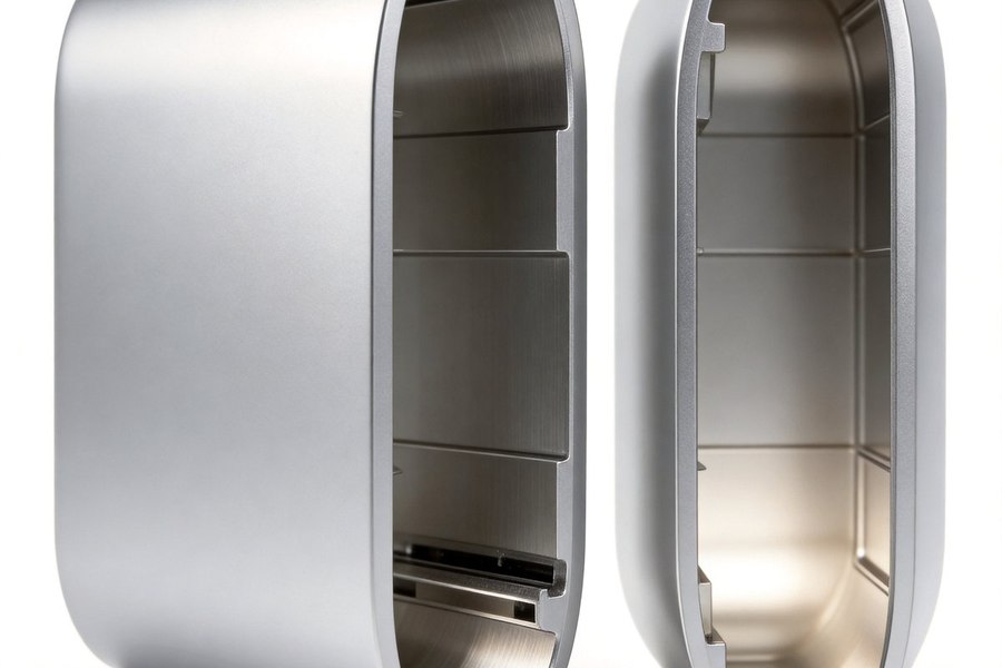
Optical Module & 5G Telecom Enclosures
Tight-tolerance extruded enclosures for 400G/800G optical modules, 5G AAU heat sinks and baseband units — ±0.04 mm bores, 0.3 mm…
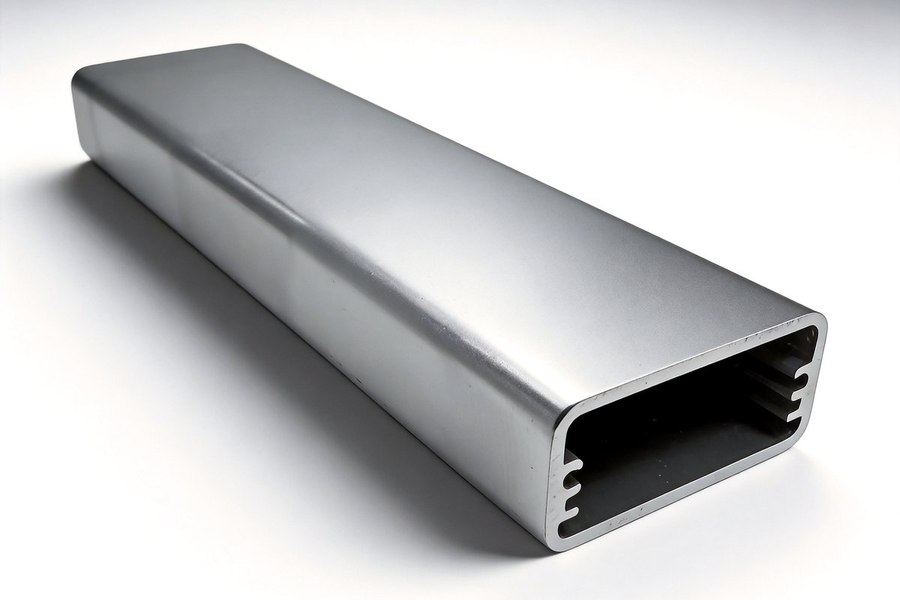
Automotive Electronics Enclosures
Vibration and temperature-cycled aluminium housings for on-board chargers, ECUs, display frames and auxiliary lighting —…
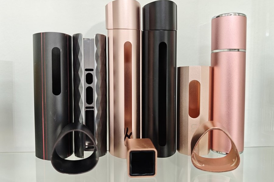
Medical & Beauty Device Enclosures
Cosmetic-grade aluminium housings for beauty instruments, hair styling tools and portable medical devices — polish-free 6063,…
3C Consumer Electronics Enclosures
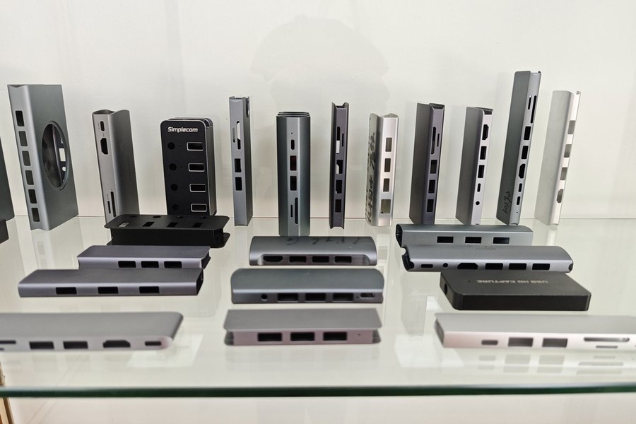
High-volume aluminium shells for external SSDs, docking stations, power banks and wireless chargers — ±0.005 mm cut-to-length…
Industrial Control & Instrument Enclosures
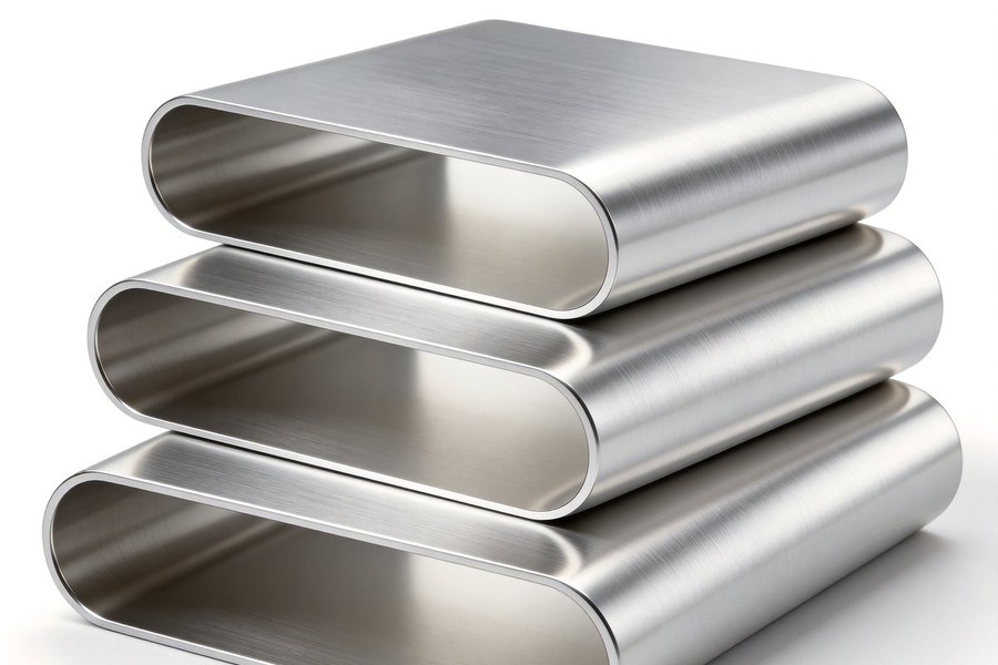
Extruded aluminium housings for PLC controllers, HMI panels, sensors and test instruments — machined cut-outs, grounding…
Send your thermal target and envelope drawings — we will come back with a fin section proposal and tooling quote within one working day.